Thursday, September 30, 2010

Building a Motor (Blog 8)

Looking at those real-life engines of automobiles and technological devices and machines amazes me. One thing that runs them is the motor. Today we created this very motor - albeit a very amateur version of it. However it was still quite an experience.
The tools and materials we used for our endeavour:

  • piece of wood
  • wine bottle cork
  • skewer
  • Lego pieces (in replacement of paperclips)
  • wires
  • pop can
  • nails
  • tape, hammer, sandpaper, thumbtacks
Before the insertion of the cork.
The first thing we did was measure the distances between the four nails to make sure they were in the right position. After we hammered the nails into their positions and placed the makeshift paperclips (Lego pieces) in its proper positions. Getting the skewer to go through the cork proved to be a difficult task. We came up with the conclusion of hammering a nail inside the middle of the cork to make the hole more easily accessible. After some necessary force, we finally got the skewer in through the cork. It was pretty straightforward after this step. 

Before the insertion of the brushes.
We put the brushes (pieces out of a V8 can) into its positions and with a little bit of adjustments we were able to complete the project. The only thing left to do was test our "motor" to see if it worked. We went up to the front to get our motor tested.

As you can see from the video, our motor was successful - we were the fifth group to complete the task. Our final product looked like this:
In retrospect, it was a rather fun activity - it was both fun and educational at the same time. Those kinds of activities seldom come, so it will probably be one of the more memorable in-class school projects this year.

Wednesday, September 22, 2010

Right Hand Rules (Blog 7)

Today we learned about two important components of magnetism in class: right-hand rule #1 and right-hand rule #2.
Firstly, Oersted's Principle states that electric charge moving through a conductor creates a circular magnetic field around the object. Thus, right hand rules are used to determine the magnetic forces around an object.

Right-Hand Rule #1:
Grasp the object (conductor) and make sure your thumb is pointing in the direction of the current direction (conventional flow). Curve your fingers inwards and that will tell you the direction of the magnetic field.


Right-Hand Rule #2:
Grasp the object with curved fingers in the direction of the flow. The thumb represents the North direction.

Tuesday, September 21, 2010

Notes on Magnetism (Blog 6)

page 582 - 589


Several points on our new unit, magnetism:

  • a magnetic field is the distribution of a magnetic force in the area of a magnet
  • two different characteristics of magnetics: north and south --> responsible for magnetic forces
  • north and north (thus, south and south too) magnetic poles repel one another while the opposite poles attract
  • a test compass is a tool to map a magnetic field
  • the Earth is similar to a magnet, since it produces its own magnetic field
  • ferromagnetic metals are metals that are not magnetic, but attract; ex. iron, nickel, and cobalt
  • the Domain Theory of Magnets: all large magnets are made up of many smaller and rotatable magnets, called dipoles, which can interact with other dipoles close by; if dipoles line up, a small magnetic domain is produced
  • Oersted's Principle: charge moving through a conductor produces a circular magnetic field around the conductor
  • RHR #1
  • right-hand rules: hand signs to help predict how magnetic forces act
  • right-hand rule #1 (RHR#1) for conventional current flow: grasp the conductor with the thumb of the right hand pointing in the direction of conventional (positive) current flow; the curved fingers point in the direction of the magnetic field around the conductor 
  • RHR #2
  • right-hand rule #2 (RHR#2) for conventional current flow: grasp the coiled conductor with the right hand such that curved fingers point in the direction of conventional current flow; outside the coil, the thumb represents the northern end of the electromagnet produced by the coil 
  • factors that affect a magnet's strength: current in the coil, number of turns in the coil, type of material in the coil's centre, and the size of the coil

Wednesday, September 15, 2010

Notes on Resistance (Blog 5)

September 14, 2010
pages 553-563


Some points I found useful during my reading:

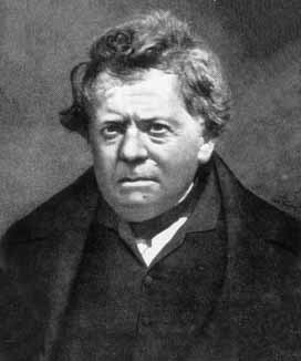
Ohm, a very handsome man
  • the amount of energy (current flow) in a circuit that is transferred to a device relies on the potential difference of the power supply and the nature of the path through the electric potential energy-using loads
  • the more difficult the path in a circuit, the more opposition there is to flow - called resistance
  • resistance is measured in ohms (Ω); named after Georg Simon Ohm, a German physicist 
  • the formula for resistance is R = V / I; V is the potential difference and I is the current
  • Ohm's law: the V / I ratio is constant for a certain resistor; in order to prove Ohm's law, you will need to measure data, plot the data, find the slope, and then create an equation
  • factors that determine resistance depend on the properties of the conductors; the length, cross-sectional area, the material, and the temperature of a conductor affect resistance (eg. thin wire has a large resistance compared to a thick wire)
  • the gauge number of a wire tells us its cross-sectional area; a small gauge number has a large cross-sectional area, and vice versa
  • superconductivity: the ability of a material to conduct electricity without heat loss due to electrical resistance
  • series and parallel circuits were studied by Gustav Robert Kirchhoff, a German physicist; his studies led to Kirchhoff's laws
  • Kirchhoff's current law: the total amount of current into a junction point of a circuit = the total current that flows out of that same junction
  • The resistance formula triangle.
  • Kirchhoff's voltage law: the total of all electrical potential decreases in any complete circuit loop is equal to any potential increases in that circuit loop

Monday, September 13, 2010

Ohm's Law: Reference Chart (Blog 4)

The Energy Ball (Blog 3)


September 10th, 2010

Our class received two objects: an envelope full of smiley faces with questions written on them and an "energy ball," which was apparently an extremely expensive ping pong ball. The twelve questions were to be answered; to the best of my ability I have done so:

1. Can you make the energy ball work? What do you think makes the ball flash and hum?
The energy ball works when I touch both metal contacts with my fingers. This is because my body is a conductor of electricity, with all its charged ions inside. As both contacts are touched, I complete the circuit, making the ball flash with noises.

2. Why do you have to touch both metal contacts to make the ball work?
If I do not touch both metal contacts, I will not complete the circuit, and therefore the electricity will not pass through and go back to its power source. Without a complete circuit, the ball will not light up.

3. Will the ball light up if you connect the contacts with any material?
The material that you use to connect the metal contacts is the vital source of whether or not the ball will light up. The material definitely cannot be insulators such as rubber, plastic, or glass, as they do not conduct electricity. If they do not conduct electricity, the circuit is not complete and thus the ball will not light up.

4. Which materials will make the energy ball work?
Most types of metal such as silver, copper, nickel, and gold will conduct electricity and therefore make the energy ball work. 

5. This ball does not work on certain individuals - what could cause this to happen?
This was a puzzling question at first, but with further thinking, answers came upon me. I believe if someone's skin is extremely dry, it will not conduct electricity. The contact point of the metal contact and the person's finger will not transfer any electrons because of the dry nature of the finger. Without the transferring, the circuit will not be complete and the ball will not work.

6. Can you make the energy ball work with all 5-6 individuals in your group? Will it work with the entire class?
Yes, if every member in our group has physical contact with each other's skin, and each metal contact on the ball is touched by a different person, the ball will light up. It worked with the entire class as well since it is the same circuit, except bigger or longer. Fortunately no one in our class proves question number five correct, and the electricity is transferred through every individual.

7. What kind of circuit can you form with one energy ball?
With one energy ball, a simple circuit can be formed. It can have an open/closed switch when I put my finger on the contact point.

8. Given 2 balls: Can you create a circuit where both balls light up?
Two energy balls can definitely simultaneously light up. By using at least two people (although difficult, one person could be possible too), two balls can light up if each contact point is touched with any finger. As long as each contact point is touched, the circuit is complete and both balls light up.

9. What do you think will happen if one person lets go of the other person's hand and why?
If one person lets go of the other person's hand (or pinky in this case), the circuit will not be complete and the flow of electrons will not carry on. Thus, the energy ball will evidently not light up.

10. Does it matter who lets go?
No, it doesn't matter who lets go because as long as one connection is lost, the circuit will not be complete.

11. Can you create a circuit where only one ball lights (both balls must be inclined in the circuit)?
Yes, a parallel circuit must be made for this to occur. One circuit will be running continuously as the other one opens and closes. With this happening, one ball will be lit while the other will be off, even with both inclined in the circuit.

12. What is the minimum number of people required to complete this?
In class, the minimum number of people that tried it was six people, but it would probably work with less than four people, as long as they are all capable and cooperative.


Parallel and Series Circuits
As talked about above, parallel circuits are basically two simple circuits side by side. Both circuits share one "line" of wire, so to speak. Staying true to its name, parallel circuits have their loads and resistors placed parallel to each other in the circuit, as seen in the diagram to the left.


Series circuits are basically a series of simple circuits whose loads and resistors are connected one after another in one direction.


The difference between series and parallel circuits.

Friday, September 10, 2010

Tall Structures (Blog 2)

Challenge
     Yesterday during class we underwent our first challenge - to build the tallest newspaper structure in the class. Upon hearing it, it did not seem like a difficult task to conquer. However, I was proven blatantly wrong.
     In groups of three or four, our class had twenty minutes to attempt our first shots at architecture and engineering with five pieces of newspapers and a limited supply of masking tape. The first and overall mistake we made was not planning our structure well enough. Although we did talk about how we were going to shape the newspaper, the time we took for that was far too short and we should have allotted some more time for the planning portion of the challenge.
     The reason our structure was unsuccessful in terms of physics was because the foundation did not have enough support and the weight distribution were in the wrong areas. We should have applied more newspaper to the base of the structure so it could hold up the remaining newspaper and tape. As we sadly figured out, the structure kept falling over because of the weak base despite the amount of changes we made to it. In the end our structure measured about 20 centimetres while the winning structure measured around 185 cm. Although our newspaper structure lacked in height, we were not in last place and we had fun making it.


My group members holding up what our structure would have looked like if it had been stable.


Tall Structures
     Tall structures obviously wouldn't be as stable as smaller, shorter structures if they were built the exact same way - they would topple over and be demolished in seconds. Therefore, we would need to figure out what exactly makes a tall structure stand still.
     First of all, there should be a low centre of gravity so most of the weight is distributed on the bottom. That would mean the top would not fall over (that easily). Secondly, the foundation or the base of the structure should ideally be as large as possible to insure its stability. As each story on a building progresses, it can become gradually slimmer - but always make sure the base is thick and strong.
     Another characteristic to make a structure more stable would be to use triangles, as they are the strongest shape. They either expand or contract, so they will not bend and break. 


The Eiffel Tower uses the idea of building from a large base to a slim top.


Top Thrill Dragster - 420 ft, 120 mph
     The above roller coaster broke records in 2003 when it was unveiled for both height and speed. It has now been surpassed by a similar coaster, but it still remains second. How could such a tall roller coaster be standing without toppling over? As you can see, the yellow supports adjacent to the track hold it up, and the shape the supports form are triangles. This utilizes the effect of how triangles are the sturdiest shape.

The Centre of Gravity
     The centre of gravity is the point around which a body's weight is equally balanced in all directions. It keeps an object balanced and stable. Symmetry is important when it comes to the centre of gravity and stability. If an object is toppled to the side a bit, the centre of gravity will shift  to make sure the mass is evenly distributed throughout the object, but inevitably it will topple over.

Wednesday, September 8, 2010

Notes on Current Electricity (Blog 1)

Wednesday, September 8, 2010
Physics textbook: pages 544-552

  • a flow of electrons is called an electric current
  • a current, much like a water current, flows from a positive terminal to a negative terminal
  • equation for a current: I = Q/t, where I represents current in amperes, Q represents the quantity of the current, represents time in seconds
  • an ammeter is used to measure currents of two types: direct current (DC) and alternating current (AC)
  • DC: the current flows in one direction from a power supply (ex. battery) to the load (ex. lightbulb), then back to the power supply
  • AC: the current has electrons that reverse because of electric and magnetic fields; the path of the current is also known as a circuit
  • the equation to show the electric potential difference used is V = E/Q; V is the electric potential difference in volts, E is energy in joules, and Q is the charge in coulombs
  • the equation E = Vlt calculates the energy transferred by charge flow
  • a voltmeter is used to measure potential difference
  • throughout the world, there are many different ways to convert energy from chemical, mechanical, thermal, and light to electric potential energy; wind, coal, oil, nuclear plants, and solar energy, among many examples, may be used